
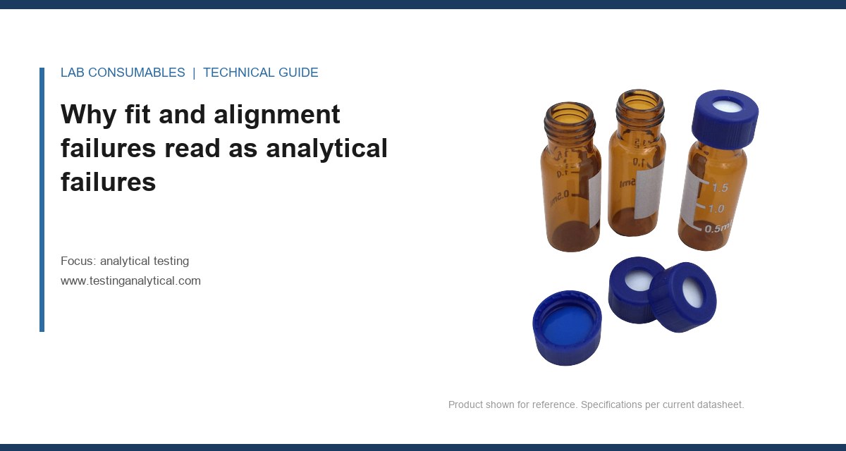
Last spring a QC analyst called me about a failing USP <621> assay on a compounded cream. The method was validated, the column was new, the standards were fresh, and the system suitability on the previous shift passed. The next morning, three injections in a row came back at 92 to 94 percent of label, with an RSD that drifted from 0.8% to 2.6% across the run. Nobody had touched the method. What had changed was that the vial tray had been reloaded by a different technician, and the autosampler needle was bottoming out about 0.6 mm deeper than it should have. The needle was clipping the shoulder of the glass, the septum was being pierced off-center, and the resulting partial injections were reading as a potency failure. The fix took four minutes with a tray height gauge. The investigation took three days.
That is the pattern I want to write about here. Fit and alignment problems do not announce themselves as mechanical issues. They show up as analytical failures: failing system suitability, drifting retention times, tailing peaks, phantom carryover, out-of-spec potency, and audit findings that point at the method when the method was never the problem. If you run a lab, the fastest way to cut investigation time is to know which failure signatures belong to fit and alignment rather than chemistry.
The reason these problems are so hard to catch is that every analytical result passes through a mechanical interface before it reaches a detector. The sample has to be drawn from a specific point in a specific volume of liquid, transported through tubing of a specific internal diameter, injected through a septum at a specific point, and delivered onto a column inlet at a specific depth. Each of those steps has a tolerance. When the tolerance is exceeded, the chemistry does not change, but the physics of the injection does, and the detector cannot tell the difference between “the sample is weaker” and “we injected less of it.”
I have seen this misdiagnosed as method failure, column failure, detector drift, and even standard degradation. All four investigations cost time and consumables. None of them found the actual cause, because the actual cause was a 0.5 mm offset in a needle depth or a 1.2-degree tilt in a tray that had been dropped during cleaning.
The other reason these failures are insidious is that they often pass system suitability on the first injection. Fit problems frequently have a position dependence: the first few vials in a tray are fine, the middle of the tray drifts, and the last vials fail. If your SST injection comes from position 1 and your samples come from positions 40 through 60, you can validate the run and still fail the batch. That is not a method problem. That is a mechanical problem that the SST protocol was never designed to catch.
The eight fit and alignment failure modes I see most often
These are the ones that come up repeatedly across HPLC, GC, and LC-MS workflows. I have ranked them roughly by how often they show up in a routine lab, not by how dramatic they are.
1. Needle depth and vial bottom geometry mismatch
This is the single most common fit problem I deal with. A standard 2 mL HPLC vial has an internal height of about 32 mm from the crimp or screw thread to the inside bottom, and the bottom is almost never flat. Most glass vial bottoms are either conical (a shallow cone with a radius of about 1.5 mm at the tip) or rounded. The autosampler needle has a specified depth range, and if the needle is set to draw from a fixed height rather than a bottom-sensing mode, it can either miss the liquid entirely (causing a low-volume draw) or strike the glass (causing a bent needle, a partial septum punch, or a chip of glass in the sample).
The failure signature is a progressive loss of peak area across a tray, often with an increase in RSD. If you plot peak area against vial position, you will see a slope. If the slope correlates with the physical position in the tray, it is a fit problem, not a chemistry problem. The check I recommend is simple: pull the tray, set a single vial at position 1, position 30, and position 60, and inject the same standard from each. If the areas differ by more than 1%, you have an alignment issue.
For 2 mL vials, the standard reference is the 12 x 32 mm format, and the GPI 8-425 or GPI 13-425 thread depends on the closure system. The thread is not interchangeable. A 13-425 cap on an 8-425 vial will cross-thread and produce a seal that passes visual inspection but leaks under autosampler vacuum. If you want to read more on the physical format of these parts, the reference material at Vial for HPLC covers the dimensional tolerances in detail.
2. Septum piercing point drift
A septum is designed to be pierced at or near its center, and the silicone or silicone/PTFE laminate is thickest and most uniform at that point. When the needle strikes off-center, three things happen. First, the puncture is closer to the crimp ring, where the seal is thinner and the glass-to-septum interface is less supported. Second, the needle can catch the edge of the septum and tear a slit rather than punch a clean hole, which produces coring and a slow leak. Third, the puncture count per septum drops. A well-aligned autosampler can get 50 to 100 punctures from a quality silicone septum before leakage; an off-center needle can fail in 10 to 15.
The analytical symptom is carryover and a gradual loss of injection volume, which shows up as declining peak area and, in GC, as a broadening solvent front. The fix is to verify needle alignment against the septum center with a calibration plate, and to check the septum retainer torque. For a 13-425 screw cap, the recommended torque is about 1.5 to 2.0 inch-pounds. Over-tightening distorts the septum and shifts the effective center.
3. Column inlet depth and ferrule seating
On the column side, the fit problem is the depth at which the capillary or the tubing is inserted into the column inlet. For a standard 1/16 inch fitting, the tubing must seat fully into the ferrule and the ferrule must seat fully into the column end fitting. If the tubing is cut short by even 1 mm, or if the ferrule is not fully seated, a dead volume forms at the column inlet. That dead volume produces peak broadening (a classic “shoulder” on the first eluting peak), a shift in retention time, and, in severe cases, a complete loss of resolution between critical pairs.
I have seen this misdiagnosed as “column degradation” more times than I can count. The column is fine. The ferrule was seated at an angle, or the tubing was cut with a worn cutter that left a burr. The fix is to cut tubing with a proper cutter, inspect the cut face under a loupe, and use a ferrule seating tool. If you do not have a seating tool, the standard trick is to insert the tubing, tighten the nut finger-tight, then push the tubing forward while tightening the nut the final quarter turn.
4. Detector flow cell alignment
In UV and PDA detectors, the flow cell has a fixed path length and a fixed optical alignment. The cell is held by a bracket, and the bracket has a tolerance. When the cell is not seated fully, or when the bracket has been bent during a lamp change, the light path is partially occluded. The result is a loss of sensitivity (lower slope on the calibration curve), increased baseline noise, and, in some cases, a refractive index artifact that looks like a ghost peak.
The diagnostic is to run a standard at a known concentration and compare the response factor to the historical value. A drop of more than 10% in response factor, with no change in retention time, points at the flow cell or the lamp, not the column. The fix is to reseat the cell and confirm the bracket screw torque. On most instruments, that is a 2 mm hex screw at about 5 inch-pounds. Do not over-torque it; the bracket is aluminum and will strip.
5. Autosampler tray and carousel level
The tray or carousel that holds the vials has to be level within a tolerance, usually about 0.5 degrees. A tray that has been dropped, or a carousel that has been removed and reinstalled without seating, will introduce a tilt that changes the effective needle depth across the tray. The failure signature is position-dependent, like the needle depth problem, but it is often worse at the edges of the tray than in the center.
I keep a small machinist’s level in the lab for exactly this check. It takes 30 seconds and it has saved me more than one three-day investigation. If the tray is out of level, reseat it and check the mounting screws. If the carousel is warped, replace it. A warped carousel is not worth trying to shim.
6. Guard column and inline filter fit
Guard columns and inline filters are the parts most often installed by hand, and the most often installed at an angle. A guard column that is cross-threaded will produce a partial seal, which shows up as a pressure spike on injection and a slow baseline drift. An inline filter that is not fully seated will produce a small dead volume that broadens early peaks. Both are easy to miss because the leak is small enough that it does not drip, but large enough to affect the run.
The check is to look at the system pressure trace during the first 30 seconds of the run. A properly seated guard column and filter produce a flat pressure trace. A misaligned one produces a 5 to 20 bar spike that settles after the injection. If you see that spike, stop the run and reseat the fittings.
7. GC liner and inlet seal alignment
In GC, the liner sits in the inlet and is sealed by an O-ring or a graphite ferrule. If the liner is not fully seated, or if the O-ring is the wrong durometer, the inlet leaks. The symptom is a loss of sensitivity and a shift in retention time, especially for early-eluting compounds. The leak is often small enough that a pressure decay test passes, but large enough to affect the split ratio.
The fix is to verify the liner depth against the manufacturer’s specification (typically 1 to 2 mm below the inlet body top), and to use the correct O-ring durometer. For most inlets, that is a 70 durometer Viton or a 70 durometer graphite. A 90 durometer O-ring will seal but will not compress enough to seat the liner fully.
8. Syringe and needle seat alignment in the injector
The injector syringe has a needle that seats into a needle seat, and the seat has a specific alignment. If the syringe is not fully seated in its holder, or if the needle is bent, the injection volume will be short or inconsistent. The failure signature is a low peak area with a high RSD, often worse on the first injection of a run than on later injections.
The check is to remove the syringe, inspect the needle for a bend (a loupe helps), and reseat it. If the needle is bent, replace it. A bent needle is not worth trying to straighten; the seat will be damaged by the time you get it close.
Comparison checklist: fit and alignment versus chemistry failure signatures
The single most useful tool I have for triage is a short table that maps the symptom to the likely cause. If the symptom pattern matches the left column, stop looking at the method and start looking at the hardware.
- Position-dependent peak area: fit and alignment (needle depth, tray level, carousel tilt). Chemistry failures are usually position-independent.
- High RSD with a normal mean: fit and alignment (partial injections, short draws). Chemistry failures usually shift the mean as well.
- Peak area slope across a tray: fit and alignment. A slope of more than 1% across 60 positions is a mechanical problem.
- Retention time shift with no change in peak shape: fit and alignment (dead volume, guard column seating) or temperature. Chemistry failures usually change peak shape too.
- Peak broadening with a normal retention time: fit and alignment (column inlet depth, ferrule seating, inline filter).
- Carryover that appears only on certain positions: fit and alignment (septum coring, needle wipe). Chemistry carryover is usually position-independent.
- Pressure spike on injection: fit and alignment (guard column, filter, fitting).
- Response factor drop of more than 10% with stable retention time: detector flow cell alignment or lamp, not the column.
- Uniform low recovery across all positions: chemistry (standard, extraction, dilution). This is the one pattern that usually is a method problem.
- Uniform high RSD across all positions from the first injection: chemistry or instrument, not fit. Fit problems usually build across the run.
I have used this checklist for years. It is not perfect, but it shortens the average investigation from days to hours. The key insight is that fit problems are almost always position-dependent or run-order-dependent, while chemistry problems are usually uniform. If you see a pattern that changes across the tray, start with the hardware.
Operational precautions that prevent most of these failures
Most of the fit and alignment problems I see are preventable with a small number of habits. None of them are expensive. All of them require someone to actually do them.
Use a tray height gauge on every tray change
A tray height gauge is a machined block that sits in the tray and confirms the vial height. It costs less than a hundred dollars and it takes 30 seconds to use. I require it on every tray change, and I have not had a needle depth failure since I started requiring it. The gauge should be checked against a certified reference every six months.
Torque every screw cap to spec
For 13-425 screw caps, the spec is 1.5 to 2.0 inch-pounds. For 8-425, it is 1.0 to 1.5 inch-pounds. A calibrated torque wrench is the only way to hit that consistently. Hand-tightening produces a torque that varies by a factor of three between technicians, and the over-tightened caps are the ones that distort the septum and shift the puncture point. If you want a deeper look at the closure side of this, the material at Lab Vials covers the dimensional specs for the common formats.
Inspect ferrules and tubing cuts
A worn tubing cutter leaves a burr that prevents the ferrule from seating. I replace cutters every six months, and I inspect every cut under a loupe before installation. A ferrule that has been installed at an angle should be discarded, not reused. The cost of a ferrule is trivial compared to the cost of an investigation.
Log every tray change and every column change
The single biggest reason fit problems take so long to find is that nobody knows what changed. A simple log that records the date, the technician, the tray, the column, and the fittings used will cut investigation time in half. I have seen labs that log every reagent and every standard but not the hardware. That is backwards. The hardware is where the failure lives.
Run a position-dependent SST
Most SST protocols inject the standard from position 1. That is fine for chemistry, but it does not catch fit problems. I recommend a position-dependent SST: inject the same standard from position 1, position 30, and position 60, and require the areas to agree within 1%. If they do not, the run does not start. This one change has caught more fit problems than any other single habit.
Troubleshooting checklist for a failing run
When a run fails and the method is not obviously at fault, I work through this checklist in order. It takes about 20 minutes and it resolves the majority of fit and alignment failures.
- Step 1: Plot peak area against vial position. If there is a slope of more than 1%, go to step 2. If the plot is flat, the problem is probably chemistry or instrument.
- Step 2: Check the tray level. Use a machinist’s level. Tolerance is 0.5 degrees. Reseat or replace the tray if it is out.
- Step 3: Check the needle depth. Use a tray height gauge. Confirm the needle is within the manufacturer’s specified depth range for the vial format.
- Step 4: Inspect the septum and the puncture point. A puncture that is more than 1 mm off-center is a problem. Check the cap torque.
- Step 5: Check the column inlet. Inspect the ferrule seating and the tubing cut. Reseat or replace as needed.
- Step 6: Check the guard column and inline filter. Look for a pressure spike on injection. Reseat the fittings.
- Step 7: Check the detector flow cell. Compare the response factor to the historical value. A drop of more than 10% points at the cell or the lamp.
- Step 8: Check the GC liner and inlet seal (if applicable). Verify the liner depth and O-ring durometer.
- Step 9: Check the syringe and needle seat. Inspect for a bend and reseat.
- Step 10: If all of the above pass, revisit the method. At this point, the chemistry is the most likely cause.
I have run this checklist on hundreds of failing runs. About 70% of them resolve at step 2 or step 3. Another 20% resolve at step 5 or step 6. The remaining 10% are genuine chemistry or instrument problems. That distribution is the reason I put so much emphasis on fit and alignment: it is where the majority of failures actually live.
Where to source parts that hold their tolerances
The fit and alignment problem is partly a sourcing problem. A vial that is 0.3 mm out of spec on the internal height, or a septum that is 0.2 mm off-center in the cap, will produce exactly the failures described above. The tolerance stack matters, and the only way to control it is to buy from suppliers who publish their dimensional specs and hold them.
For vials and closures, I specify the 12 x 32 mm format with GPI 13-425 threads for most HPLC work, and I require a certificate of analysis that states the internal height and the septum thickness. For columns and fittings, I use the manufacturer’s own ferrules and tubing cutters; the aftermarket parts are cheaper but the tolerance stack is where the dead volume comes from. The technical resources at Agilent chromatography consumables and columns and at Thermo Fisher chromatography and sample handling publish the dimensional specs you need to check against. The application notes at Restek technical resources for chromatography are also useful for understanding how inlet geometry affects peak shape.
For regulated methods, the fit and alignment requirements are often implicit in the method but not stated. The U.S. EPA SW-846 test methods for waste and materials are a good example: the methods specify the instrument and the column, but they do not specify the ferrule torque or the needle depth. That is left to the lab, and that is where the failures live. If you are running a regulated method, the fit and alignment parameters should be in your SOP, not in the technician’s head.
For a broader view of how these parts fit into the overall testing workflow, the reference material at Chromatography Consumables and the method guidance at Analytical Testing cover the selection criteria in more detail.
Recommendation
My recommendation is to treat fit and alignment as a first-class part of method validation, not an afterthought. That means four concrete changes. First, add a position-dependent SST that injects the standard from positions 1, 30, and 60 and requires areas to agree within 1%. Second, add a tray height gauge and a calibrated torque wrench to the standard equipment list, and require their use on every tray change. Third, write the fit and alignment parameters (needle depth, ferrule torque, cap torque, liner depth) into the SOP with specific numbers. Fourth, log every tray and column change so that investigations have a starting point.
None of these changes are expensive. The gauge and the wrench together cost less than a single failed batch investigation. The position-dependent SST adds about 10 minutes to a run. The SOP update takes an afternoon. The payoff is a lab where the majority of failures are caught before they become investigations, and where the investigations that do happen start with the hardware instead of the method.
The pattern I have seen across every lab I have worked in is the same: the chemistry is usually fine, and the hardware is usually where the failure lives. A method that is validated on paper can still fail on the bench because the vial was 0.3 mm out of spec, the septum was pierced off-center, or the ferrule was seated at an angle. The fix is not a better method. The fix is a better fit, checked on a schedule, with numbers that everyone in the lab knows. If you are still chasing method failures that turn out to be hardware problems, start with the tray, the septum, and the ferrule. That is where I would look first, and it is where the data usually points.
References & further reading
Related resources from our lab consumables network:
- Analytical Testing at testinganalytical.com
- Hplc Vial at vialforhplc.com
- Chromatography Consumables at chromatographyconsumables.com
- Lab Vials at labvials.com
External references and standards: